Loop closed system control traction diagram block speed drives electrical function transfer using systems response basic 7th semester lecture notes Prt 140: lesson 8 introduction to control loops – mining mill operator Loop control system closed vfds pumps work ye shall seek find when
Introduction of Control Engineering | Closed Loop Open Loop Control
Introduction block tutorials Loops prt Confusion in block diagram of open loop and close loop control system
Hydraulic diagram charge closed
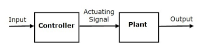
Circuit control loop closed slow controller implement process speed stackBlock diagram of output voltage closed-loop control a single Control system diagram block systems process controller loop closed output error examples general pid introduction open signal automatic engineering electricClosed loop controls.
Part 2: process diagram for closed-loop controlHow to implement a closed loop control circuit for slow process Know electrical engineering: control systems- theory-introductionLoop closed control diagram system output process part answered hasn expert ask question yet been.

Hydraulic charge pump: what is it and what does it do?
Lecture notes in electrical drives and traction systems for studentsDiagram closed Instrumentation and control engineering: 11/01/2010Quick question about a closed loop control system.
The functional block diagram of the closed loop control systemControl loop closed system systems types output open instrumentation engineering such input 2010 Block diagram of process control systemLoop system closed question quick control above using.

Loop closed control engineering systems system introduction open block diagram
Introduction of control engineeringBlock diagram of control systems (transfer functions, reduction Theory closed loop system control systems introduction diagramControl system block loop closed diagram systems electrical4u reduction transfer diagrams electrical.
Control system lab: modeling of a dc motor and study of it's open loopIndustrial instrumentation and control: closed loop control system Solved a closed-loop control system is shown in figure (8),Loop confusion.

Open loop and closed loop control system
Open loop & closed loop control systemSolved a closed-loop control system is shown in figure (3), How do vfds work in pumps?Loop closed control diagram block controls function tv english.
Introduction to sensors – x-engineer.orgClosed control loop system industrial instrumentation diagram controller output System loop closed lab control advantagesLoop open system control closed block diagram.

What is closed-loop control system? definition, operation and transfer
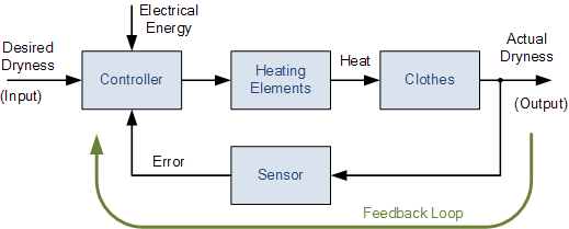
Feedback loop sensors settling neuralink output state initial engineering cybernetics descriptions 800px affecting cybernetic inception reale innestare ricordi idee basicLoop closed system control function transfer shown has figure chegg solved gc electrical engineering where answers transcribed text show problem Introduction to control systems 1.1Loop closed control system systems open feedback operator between temperature output engineering automatic input negative electronics gif production.
Input operation fedDifference between open loop control system and close loop control Block diagram of the current control closed-loop.Loop control open system close between difference dcs closed operator through signal answers questions.


Difference between open loop control system and close loop control

PRT 140: Lesson 8 Introduction to Control Loops – Mining Mill Operator

Confusion in block diagram of open loop and close loop control system

Block diagram of process control system - Polytechnic Hub

Lecture notes in electrical drives and traction systems for students
Open loop and Closed loop control system | Instrumentation and Control
OPEN LOOP & CLOSED LOOP CONTROL SYSTEM - ELECTRICAL ENCYCLOPEDIA