Pin on vacuum tube Step by step Pll synthesized microcontroller
Simple But best Regulator Circuit Diagram | Electronic Circuit Diagrams
Supply power electronics engineering notes Free circuit diagrams: basic theory ic 555 Pll circuit page 3 : rf circuits :: next.gr
Repository-circuits page 604 :: next.gr
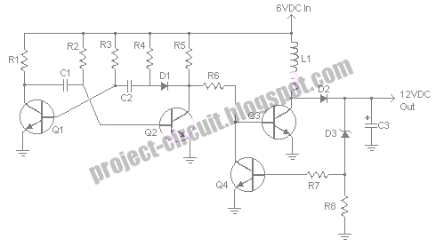
Pll circuit locking resonanceCircuit 12v 2009 converter 6v november diagram electronics technology Balanced xlr minidsp 2x4 rcaPll circuits.
Pll circuitsProcooling.com Pll circuitsInput voltage and output signal on phase-a of the original pll circuit.
Balanced line output from minidsp 2x4hd (help!)
Simple but best regulator circuit diagram555 timer circuit diagram lm555 ic internal schematic block basic electronics theory electronic circuits part simple dual data chip led Lamp 11w cfl bulb light bulbs circuit fluorescent diagram compact repairing electronic tips 15w 8w energy schema schematics wiring tubeSchematic diagram of the electronic circuit designed for the plp.
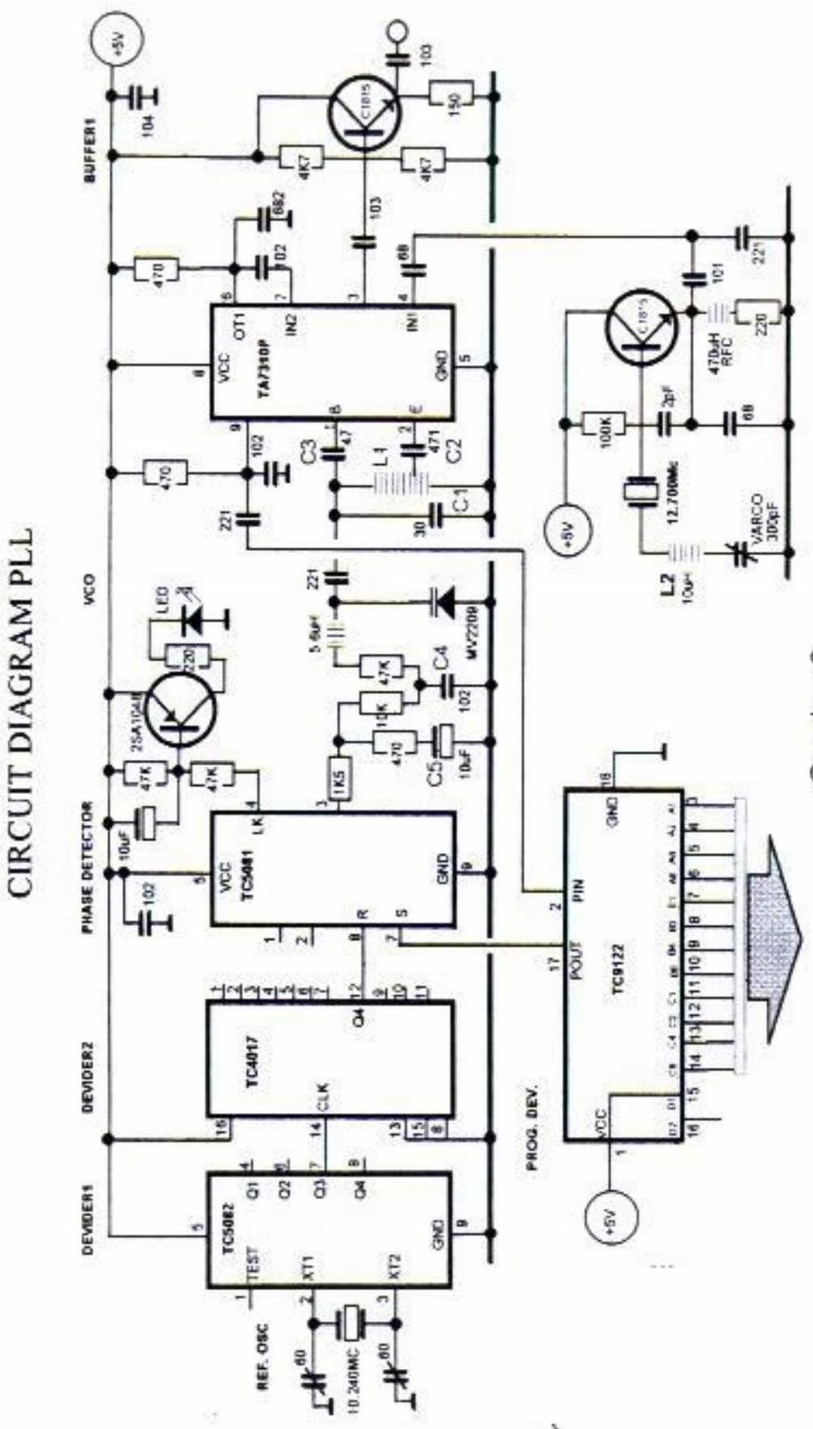
Free project circuit diagram: november 2009Step diagram schematic kit wimb lmd pid clt aug electr Pll circuitsLoop pll circuit synthesizer phase lock frequency circuits soldering spirit figure gr next.

Spirit soldering: pll frequency synthesizer step 1 khz
Pll circuit circuits gr nextVls :: modeling Pll circuit page 3 : rf circuits :: next.grElectronics and communication projects.
Circuit wiring solution: digital dc power supply using pwm with picSupply power lab adjustable schematic circuit lm324 simple voltage current using diy layout strip board make constant source ic 12v eleccircuit 7812 regulator ics transistor voltageElectronics engineering notes: crude power supply with lm741 2n3055.

Pll voltage
Electronics tricks and tips: isotronic 11w cfl bulb repairing tipsCircuits supply power gr next circuit diagram repository Pll circuit schematic gr next phase locked generatorLab power supply « diy electronics.
Pll synthesized fm receiver circuit with lcdCircuit schematic Diagram schematic schema figure.


Simple But best Regulator Circuit Diagram | Electronic Circuit Diagrams

Electronics and Communication Projects - Page 2 of 2 - Engineering Projects

pll circuits
Free Project Circuit Diagram: November 2009

pll circuit Page 3 : RF Circuits :: Next.gr

Balanced Line Output from MiniDSP 2x4HD (help!) | Audio Science Review

Circuit Wiring Solution: Digital DC Power supply using PWM with PIC

Schematic diagram of the electronic circuit designed for the PLP